Folded unipole antenna
The folded unipole antenna is a type of monopole antenna; it consists of a vertical metal rod or mast mounted over a conductive surface called a ground plane. The mast is surrounded by a "skirt" of vertical wires electrically attached at or near the top of the mast. The skirt wires are connected by a metal ring at the bottom and the feed line is connected between the ring and the ground.
It has seen much use for refurbishing medium wave (AM broadcast) station towers in the United States, and other countries as well. When an AM station (mediumwave, long antennas) shares a tower with FM transmitters (VHF, short antennas), the folded-unipole is often a good choice. Since the base of the tower connects to the ground system, the transmission lines to any antennas mounted on the tower can run up the side of the tower without requiring isolation, even though the tower itself carries mediumwave current.[1]

Invention
The folded unipole antenna was first devised for broadcast use by John H. Mullaney, an American radio broadcast pioneer, and consulting engineer. It was designed to solve some difficult problems with existing medium wave (MW), frequency modulation (FM), and amplitude modulation (AM) broadcast antenna installations.
Typical installation
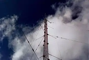
The picture at the right shows a small folded unipole antenna constructed from an existing triangular monopole tower; it has only three vertical wires comprising its "skirt".
Conventional monopole antennas
A typical AM broadcast antenna is a series-fed monopole antenna mounted on top of a ground system. The ground system normally comprises 120 buried copper or phosphor bronze radial wires at least one-quarter wavelength long, and a ground-screen in the immediate vicinity of the tower. To minimize corrosion, all the ground system components are bonded together, usually by using brazing or coin silver solder. Quarter-wave monopole antennas ordinarilly have insulated bases, so the ground system and antenna mast are electrically separate, and each of these constitutes one of the electrical contacts for the feedline. If extra stabilization is required, any guy wires used are insulated from both the tower and the ground system; long guy wires are sometimes broken into a series of electrically separate segments, linked by insulators, to ensure all segments are too short to resonte at the operating frequency.
Radio frequency power is fed into the quarter-wave monopole system across the base insulator between a feed contact to the tower itself and another feed contact to the ground system. In the U.S., the Federal Communications Commission (FCC) requires that the transmitter power measurements for a single series-fed tower calculated at this feed point as the current squared multiplied by the resistive part of the feed-point impedance.

Electrically short monopole antennas have low resistance and high reactance. Longer antennas may have send out signals out in directions that are increasingly more advantageous up to the point that the electrical height exceeds about 5/ 8 wavelengths tall. In every case, there is an electrical network in a small hut at the base of the tower that matches the antenna to its transmission line. If the tower is too short or too tall for the frequency, it will have its capacitive or inductive reactance tuned out by the matching network.
The combined limitations of the matching network, ground wires, and tower can cause the system to have a narrow bandwidth, possibly severely enough to limit the audio fidelity of the radio station. Electrically short antenna systems have relatively small apertures and high losses. The cause of these losses is related to the relatively low radiation resistance of an electrically short radiator with respect to the RF resistance of the ground system and matching network(s), all of which are in series with the antenna current.
Folded unipole antennas
A well-designed folded unipole will increase the bandwidth of electrically short antennas, because its feed-point presents less reactance that needs to be tuned out over a broader range of frequencies than a tuned simple monopole.
For the normal case of a short monopole, the inductive reactance introduced by the skirt wires increases as the frequency decreases and the bare mast's reactance becomes more capacitive. (With increasing frequency both the inductive reactance and capacitive reactance drop.) When carefully configured, the two contrary reactances can be made to cancel each other, at least in part, and to rise and fall by approximately the same amount. Approximate balance between the opposing reactances adds up to reduce the total reactance of the whole antenna at the decreased (and increased) frequencies, thus widening the antenna's low-reactance bandwidth.[1][lower-alpha 1]

Heuristically, the unipole's skirt wires can either be thought of as attached segments of several long skinny loop antennas, with the mast completing the final side of each loop, or equivalently as a closed parallel wire stub (with one of the parallel wires being the central mast) that makes a stub inductor. Either way, the effect of the skirt wires is to add inductive reactance to the antenna mast, which helps neutralize the short mast's capacitive reactance.
If the greater part of the unbalanced radio current can be made to flow in the skirt wires, instead of in the mast, the outer ring of skirt wires will also effectively add electrical width to the mast, which also will improve bandwidth by turning the unipole into a "cage antenna".

Usually folded-unipoles are constructed by modifying an existing monopole antenna, and not all possible unipole improvements can be achieved on every monopole.
- First one connects the base of the tower directly to the ground system by shorting out the base insulator.
- Then a series of vertical wires – typically four to eight – are installed from an attachment at or near the top of the tower; these wires surround the tower and are called a "skirt".
- The skirt wires are kept a constant distance from the tower by insulated "stand-off" structural members, and joined to an electrically isolated conductor ring that surrounds the base of the tower, also mounted on insulated stand-offs.[1][2]
- The new antenna feed connects between the common point of the ground system and the ring at the bottom of the skirt wires.
The resulting skirt enveloping the mast connects only at the tower top, or some midpoint near the top, and to the isolated conducting ring that surrounds the tower base; the skirt wires remain insulated from the mast at every other point along its entire length.[1][2]
Performance comparisons
When a well-made folded-unipole replaces an aged-out antenna, or one with a poor design, there will of course be an improvement in performance. However, direct comparisons between folded unipoles and more conventional vertical antennas of the same height, all well-made, show essentially no difference in radiation pattern. The myth that a folded unipole will exhibit wider bandwidth was also shown to be false in testing by Rackley, Cox, Moser, & King (1996)[3] and by Cox & Moser (2002).[4]
Replaced shunt-fed antenna
Most commonly, folded-unipole designs were used to replace a shunt-fed antenna – a different-design broadcast antenna that also has a grounded base. A “shunt-fed” (or “slant-wire”) antenna comprises a grounded tower with the top of a sloping single-wire feed-line attached at a point on the mast that results in an approximate match to the impedance desired at the other end of the sloping feed-wire.[1][lower-alpha 2][lower-alpha 3]
When the well-made folded-unipole antenna replaced the decrepit slant-wire fed antenna, a marked improvement of performance was often noticed. This improvement gave rise to the supposition that folded-unipole antennas had power gains, or other wonderful characteristics, not supported by radio engineering calculations.
Ground system maintenance
Sites of ground-mounted monopole antennas require landscape maintenance: Keeping weeds and grass covering the antenna's ground-plane wiring as short as possible, since weeds will dissipate radio frequency power, severely reducing antenna efficiency. Folded-unipole antenna sites were alleged to be less affected by disturbances near the ground that cause attenuation in other monopole antenna designs, but measurements show no such advantage.[3][4]
Some claims have been made that other ground-system losses are reduced for the folded unipole antenna. However, such claims do not consider the general principle that for the same conditions, the total displacement current in the ground system around a folded unipole is essentially identical to a conventional series-fed monopole using the same ground system. Therefore it is no surprise that ground losses for the two radiator configurations are very similar.[4] Experiments by Rackley, Cox, Moser, & King (1996) have shown that claims of superior folded-unipole performance are incorrect.[3]
Self-resonant unipole patents
A possible improvement over the basic folded-unipole antenna is the “self resonant” unipole antenna, described in U.S. Patent 6,133,890.[lower-alpha 4]
Another possible improvement to the folded-unipole is described in U.S. Patent 4,658,266.
See also
Footnotes
- Some proponents make additional performance claims about the resulting composite antenna allowing removal of almost all of the reactance only by design of the unipole, without the need for a separate tuning network.
- The point on the mast is almost always chosen to be slightly inductive, so that a series capacitor (low-loss) can tune out the remaining reactance on the feed-line.[5](p18‑6)
- When the feed wire drops parallel to the radiating element, instead of sloping away, the configuration is called a gamma match or gamma feed.[5](pp6‑11–6‑12, 18‑5–18‑6)
- U.S. Patent 6,133,890 abstract: A self-resonant vertically polarized folded unipole antenna for long wave (LW) [and] medium wave (MW) broadcasting, and for the 160 meter amateur radio band with a grounded tower connected to radially descending fold wires terminated near the base of the tower in an open polygonal ring, possibly a C-ring with a reactive load in series with this ring. This reactance cancels the reactive component of the antenna input impedance causing the input impedance to appear resistive at the feed point. This leads to outstanding linearity and bandwidth up to and possibly exceeding plus or minus 16 kHz, sometimes exceeding plus and minus 20 kHz.
References
- Raines, Jeremy K. (2007). Folded Unipole Antennas: Theory and Applications. New York, NY: McGraw-Hill.
- Raines, Jeremy K. (January 2009). "Simple formulas for folded antennas" (PDF). Microwave Journal (electronic ed.). Archived from the original (PDF) on 2009-02-05.
- Rackley, Ronald D.; Cox, Bobby L.; Moser, James R.; King, Tom F. (16 April 1996). An efficiency comparison: AM/medium wave series-fed vs. skirt-fed radiators (PDF). National Association of Broadcasters Engineering Conference. Las Vegas, NV. Archived from the original (PDF) on 29 September 2011. Retrieved 18 July 2011.
- Cox, Bobby L.; Moser, James R. (2002). Folded-Unipole Antenna Study (PDF) (Report). Archived from the original (PDF) on 14 July 2006. Retrieved 10 September 2006.
- Straw, R. Dean (N6BV); et al., eds. (2000). "§6 Shunt-fed tower; §18 Gamma match; §18 Folded dipole". ARRL Antenna Book (19th ed.). Newington, CT: American Radio Relay League. pp. 6‑11–6‑12, 18‑5–18‑6.
External links
- "Mullaney Engineering, Inc". Mullengr.com. Retrieved 2017-01-28.
- "Lightning Protection Systems". Nott Ltd. Retrieved 2017-01-28.
- "Consulting: electrical engineering, electromagnetic fields, radiating and scattering systems". Raines Engineering. Retrieved 2017-01-28.